| P19673 | Security in Building Automation | |
| |
|
DoS in automation systemsDoS attacks can be classified into two different categories. On the one hand, an adversary may try to interrupt the operation of a single network node by wasting its system resources (host-based DoS attacks). Typical targets of host-based DoS attacks are devices critical for system operation (e.g., key servers, firewalls), devices that concentrate automation functionality (e.g., controllers, operator workstations) or interconnection devices such as gateways and routers that provide an interconnection to other, possibly foreign networks. On the other hand, the network itself may be target of DoS attacks (network-based DoS attacks). In this case, the adversary tries to waste the network bandwidth to completely interrupt the communication between the devices located in the affected segment.In both cases, two possibilities exist to handle DoS attacks: DoS prevention and DoS detection. DoS prevention has the aim to limit the access to system resources in a way that an adversary does not have the opportunity to successfully perform DoS attacks. One opportunity to fully prevent DoS attacks is to limit the physical access to the network medium and to the devices that have an interface to the medium. In a wired network, this can be done by immuring the network cable or by locking the devices into a safe containment (physical security). Obviously, such an isolation is not always easy to achieve. Consider, for example, an IP backbone which is shared between the office LAN and the control network of the automation system. Since there is no clear separation between these two logical networks, an adversary that has access to the office LAN is able to disturb the communication of the automation system. For example, in case of wireless or powerline networks, an isolation is impossible due to the openness of the medium. Furthermore, a DoS prevention is hard to achieve if the adversaries have much more processing power than the victims. Therefore, in situations where prevention methods are inapplicable, DoS attacks shall at least be detected. Detecting methods try to discover an abnormal system behavior. After detection, it must be determined whether the abnormal situation may lead to a DoS attack. If a DoS attack is suspected, countermeasures have to be initiated to minimize the consequences, i.e., to avoid propagation to other, not yet infected, network segments. To combine the advantages of both methods, a hybrid approach is the most appropriate solution for automation systems. Therefore, such a combination of prevention and detection mechanisms is presented in the next section. A common approach to handle DoS in automation systemsThe presented solution uses a combination of DoS prevention and DoS detection. This scheme works as follows: On the one hand, system-critical devices are protected against host-based DoS attacks whenever possible. To achieve this, a prevention mechanism based on client puzzles is implemented on these devices. On the other hand, network-based as well as host-based DoS attacks that cannot be prevented with reasonable effort (e.g., that are targeted at low performance embedded devices) shall at least be detected and adequate countermeasures shall be initiated. Fig. 1 shows an example of an automation network where the above mentioned approach is used. Obviously, the illustrated automation network is only a theoretical example since such a combination of switched, wireless and line topology is uncommon. The intention is to protect system-critical and high-end devices like web gateways, operator workstations, and controllers against host-based DoS attacks using a prevention mechanism. Host-based attacks where a prevention is not possible as well as network-based ones are detected by the routers and gateways.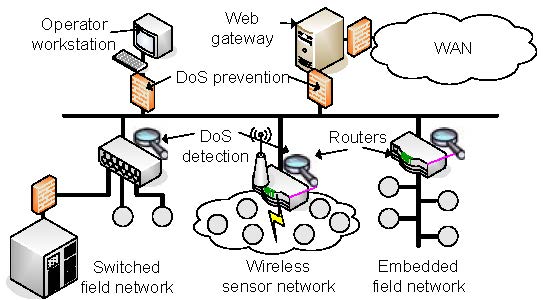 Fig.1 DoS in automation systems DoS prevention using client puzzlesTo prevent host-based DoS attacks, a client (e.g., operator workstation) that wants to set up a secured channel to a server (e.g., controller) has to prove its identity by using a two phase authentication protocol. In the first phase (pre-authentication phase), a common technique called client puzzle is used. The main objective of a client puzzle is to make a DoS attack at least as expensive for the adversary as for the target in terms of computational cost. The following client puzzle has to be solved by the client:h(C,Ns,Nc,X)=000...0k bitsY whereas h denotes a secure hash function, C the identity of the client, Ns the server's nonce, Nc the client's nonce, k the number of the hash bits that have to be 0 (i.e., the difficulty of the puzzle) and X the solution of the puzzle. The client has the objective to find the input value X which produces this hash value by brute force. As it is very easy to verify whether the solution is valid or not (e.g., by comparing the solution with pre-calculated puzzle solutions stored in a lookup table), the client must pay more computing costs than the server. If the client has solved the puzzle, the server returns an authentication ticket. Using this ticket, the client has exactly one attempt to pass the second authentication phase (secure authentication phase). In this phase, the client proves its identity using, for example, a secured password, a client certificate, or a shared secret key. If the authentication attempt fails, it has to solve another client puzzle. This scheme has the advantage that if the client has not solved the client puzzle, the server does not need to consume neither memory space nor processing power since puzzles and their solutions can be stored in simple lookup tables. Another advantage is that brute force attacks on passwords or secret keys are prevented since the attacker has only one authentication attempt after a puzzle has been solved. Furthermore, the additional effort for legitimate devices is relatively small since only one puzzle has to be solved to set up a secured channel. A typical example of such a client puzzle would be a hash value of limited length. The required complexity of the client puzzle (i.e., in this case the value of k) depends on the computational power of the involved network nodes. It must be guaranteed that it takes the client more time to solve the puzzle than the server to verify the result. However, in embedded field networks, the used microcontrollers have insufficient hardware resources to solve this puzzle within an adequate time. %For example, an attacker can easily deploy comparatively excessive processing power (e.g., by using a standard notebook PC) to perform DoS attacks. Therefore, DoS prevention using client puzzles is implemented on system-critical devices where the connecting clients are supposed to have sufficient processing power. Typical examples are the web interface of a web gateway as well as the management interface of key servers, gateways, and controllers. DoS detectionOne possibility to detect DoS attacks is the use of a so called intrusion detection system (IDS). The objective of an IDS is to detect abnormal system behavior, e.g., abnormal network traffic or abnormal device behavior. An IDS commonly consists of four components (cf. Fig. 2):
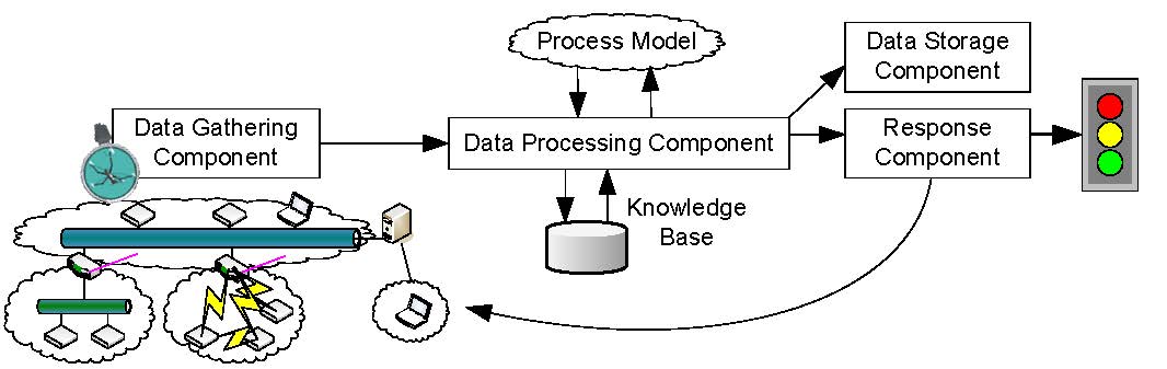 Fig.2 Intrusion detection system DoS countermeasuresAfter a DoS attack has been detected by the IDS, it is essential to minimize the resulting consequences. The most effective solution is to stop the adversary from attacking the target. To achieve this, the source(s) of the DoS attack have to be identified and isolated from the rest of the network. This keeps the system operable and prevents a propagation of the DoS attack.The most appropriate way to isolate the source(s) of the DoS attack is closely related to the physical topology of the affected network segment. As shown in Fig. 1, star (e.g., switched Ethernet networks), line, and even free topology are common in automation networks. In wired star topologies, an isolation can be accomplished by cutting the communication line to the source(s) of the attack. For example, in a switched Ethernet network, the port where a DoS attack has been detected can simply be deactivated. In wireless networks, the isolation highly depends not only on the logical topology (e.g., star, mesh) but also on the used communication model (e.g., peer-to-peer or coordinator-to-peer). The basic idea is to isolate an affected zone and to find routes that bypass this zone. However, this is currently work-in-progress and therefore not elaborated further in this paper. 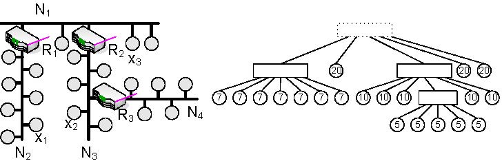 Fig.3 Device isolation Finally, in wired line or free topology, an isolation can only be achieved by decoupling the whole network segment. This action has to be executed by the interconnection device located at a network segment border. Consider, for example, device x1 in Fig. 3 starts flooding attack. If this misbehavior is detected by the IDS module running in router R1, the router can isolate network segment N2 by stopping forwarding messages to N1. Therefore, the rest of the network (i.e., N1, N3, and N4) can continue normal operation. The main drawback of this solution is that all network members of N2 become isolated. To estimate the damage a device may cause when performing a DoS attack, we define the so called DoS risk factor (DoS-RF). To calculate the DoS-RF, the network topology is represented as tree based graph. On the right hand side of Fig. 3, the corresponding graph of the example network is shown. While interconnection devices are represented as rectangular nodes, field devices are presented as circular nodes. An edge between two nodes stands for a physical network connection between two devices. Furthermore, the sequence of the children of an interconnection node defines the physical location of the device within the network segment - the left-most child is always the device located next to the interconnection device. It is assumed that the network topology is following a line topology. However, if there is free topology, the topology has to be converted to a line topology by inserting virtual interconnection nodes. The DoS-RF of a device x is now calculated as the sum of all node weights of all children and sub-children of the parent of the device x. The weight represents the damage that occurs if a device fails due to a security attack. In a first approach, the amount of data points a device holds as well as their types (e.g., safety/security critical, system, normal, low) are used to determine these node weights. Consider, for example, device x2: to isolate this device, the routers R2 and R3 have to decouple N3. This means that all members of N3 are no longer able to communicate with N1, N2, and N4. However, since there is no route from N4 to N1 and N2, also the members of N4 are only able to communicate with each other. Any communication with the other remaining, operable network segments is interrupted. Because of the severity of an attack on node x2, its sub-children of its parent node R2. While a low DoS-RF indicates that decoupling the device from the rest of the system influences only a smaller part of the network, a high DoS-RF represents the opposite. In case of an attack, a large number of devices would become isolated. To counter large DoS-RFs, a physical network segment has to be divided into smaller so called virtual network segments. Virtual network segments are not logically separated from each other i.e., they do not have a dedicated network address. Therefore, virtual network segments are invisible to network members. Dividing a physical network segment into two virtual network segments is done by placing a so called virtual bridge at these virtual segments' intersection point. A virtual bridge has two (or more) network interfaces and simply forwards incoming messages to the other network interface. However, in contrast to a layer 2 bridge, it is possible to request the virtual bridge to decouple virtual network segments by cutting the communication line between them. Consider, for example, device x3: in the original network (cf. Fig. 3), x3 has a DoS-RF of 20. However, by placing a virtual bridge between R2 and x3, the DoS-RF of x3 can be reduced to 2. This is due to the fact that now also the virtual bridge is able to decouple x3 and the device next to x3 (cf. Fig. 4). 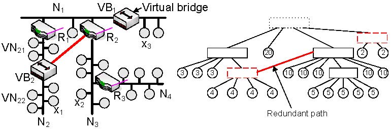 Fig.4 Virtual bridges This solution has one drawback: if a (virtual) network segment is located between two other (virtual) network segments, decoupling it also isolates all succeeding network segments from the remaining network. Consider, for example, the virtual bridge VB2 that is added in N2. This virtual bridge reduces the DoS-RF of all succeeding devices to 4. However, the devices located between R1 and VB2 still have a DoS-RF of 7 since a DoS attack within VN21 also decouples VN22 from the remaining network. To avoid this, alternative communication paths have to be provided by using redundant interconnections between virtual bridges and interconnection devices. Suppose, for example, a redundant connection is added between VB2 and R2. Using this connection, the members of VN22 are still able to communicate with the remaining network. In this case, the DoS-RF of the members of VN21 is reduced from 7 to 3. However, adding redundant connections may introduce cyclic paths. Therefore, a mechanism is necessary that only enables these redundant connections when they are required. A possible realization includes a dedicated protocol that caters for communication among all interconnection devices and virtual bridges. Thus, information on attacks can be exchanged and the most appropriate countermeasures can be triggered. An alternative solution would be to permanently enable redundant connections and to discard all duplicate messages. Furthermore, adding redundant paths may introduce additional risk. However, this risk can be eliminated by limiting the physical access to the connection (e.g., immuring the redundant connection), since redundant paths are normally point-to-point connections. The placement of virtual bridges and redundant paths is not trivial. Therefore, it has to be foreseen at installation time by the project engineer. To assist the project engineer, engineering tools shall help to find critical points (i.e., devices with high DoS-RFs) in the network topology and suggest where to add virtual bridges and redundant connections best. |
|||||||||||||||||||||||||||||||||||||||||||||||||||||||||||||||||||||||||||||||||||
|
|
With support from |
  |